Produced Water Secondary Treatment Options
Produced water systems can be divided into primary, secondary and polishing systems as shown in Figure 1.
Primary treatment equipment treats water from bulk and other process separation equipment. Effluent from the primary treatment equipment typically contains about 50 to 200 ppm oil with oil droplet sizes on the order of 50 µm.
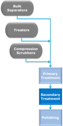
Secondary treatment equipment is designed to remove approximately 90% of the oil remaining after the primary treatment stage. In a large majority of projects, secondary treatment consists of one or more flotation units. This GATEKEEPER focuses on flotation technology.
Flotation Units
Gas flotation is a process in which gas bubbles are used for the separation of oil from water. Oil droplets attach to gas bubbles and are lifted to the water surface. The oily froth is then removed by skimming or overflowing it to a collection trough.
There are several types of gas flotation technology categorized primarily by the method used to generate bubbles. Induced gas flotation (IGF) is typically the method of choice. Dissolved gas flotation (DGF) is another method, but is rarely used in the oil industry and is not discussed here. When choosing an IGF, the main considerations are:
Mechanically vs. Hydraulically Induced Gas Flotation
Vertical vs. Horizontal Orientation
Mechanically Induced Gas Flotation
IGF units use either mechanical or hydraulic means of generating bubbles. In mechanical units, the rotation of an impeller draws gas down a stand-pipe where it comes into contact with the oily water. The impeller forces the water and gas through the disperser which creates small gas bubbles. The gas bubbles collide with the oil droplets and small solids and rise to the top of the cell where the froth flows over a weir with the assistance of mechanical paddles. The clean water flows under the baffle near the bottom of the cell.
Mechanically-driven IGF units are generally considered to have better separation efficiency than hydraulic units. Downsides include the need for a mechanical driver for each cell and a large surface area that can make it harder to control the oily water overflow on floating platforms with significant motion.
Hydraulically Induced Gas Flotation
Hydraulic IGFs replace the mechanical driver at each cell with a single circulation pump for several cells. Clean water, taken from the last cell, is injected into each cell through a nozzle designed to create a venturi effect (vacuum). The venture pulls in gas and creates small bubbles. The injected water also agitates the oily water in the cell. Mechanically driven paddles can be eliminated by using alternatives such as weirs or other level control arrangements.
Hydraulic IGFs are less expensive than mechanical IGFs and contain few or no internal moving parts, hence maintenance is simplified. Downsides for hydraulically-driven IGFs include the reduced capacity of the cell due to the recycle stream and large weir overflow rates due to motion on floating platforms.
Vertical vs. Horizontal Flotation Units
IGFs vary in orientation (vertical single cell and horizontal multi-cell) and in mechanism or bubble formation (mechanical, eductor, porous media, DGF pump).
Vertical single cell units are typically not as effective as multi-cell units. They are frequently specified on floating platforms because they are less susceptible to sloshing and usually have lower reject rates than horizontal units. Bubble generation can be via eductors or DGF pumps. Bubble generation via porous media has not proved successful.
Horizontal multi-cell flotation units typical have 2 to 4 cells with gas bubble generation. Water flows through the cells in series. Multiple cells eliminate the chance of a small percentage of the feed stream short circuiting the flotation cell as can occur in poorly designed single-cell vertical units.

Compact Flotation Units
In an effort to reduce weight and footprint, several vendors offer Compact Flotation Units (CFU). These incorporate gas flotation and inertial forces to achieve effective oil separation. These are typically vertical vessels with proprietary internal devices. Figure 2 shows the basic design of a compact flotation unit.
Using Dissolved Gas
Though dissolved gas flotation units are not frequently used offshore, produced water at separator operating pressure naturally contains dissolved gas. Some of that gas is liberated when the pressure is reduced. Effectively designed skim tanks can make effective use of this liberated gas.
Design Considerations
When designing IGF units, the following must be considered:
Steady flow to the Flotation Unit
Effective Primary Treatment
Avoid Recycling the Reject Stream
Ensure Steady Flow To The Flotation Unit
Steady flow is essential for IGF performance. IGF units do not handle slugs or varying flowrates well. Snap acting level control valves in separators should be avoided. If steady flowrates cannot otherwise be assured, a skim tank should be considered upstream of the flotation unit.
Reject Stream
The reject rate is typically 1 to 3% of the incoming stream but can be increased to 5-10% for high oil-concentrated streams. Reject streams are sometimes routed back to the separation system. This should be avoided where possible. Reject oil contains water clarifiers and flotation aids that can stabilize emulsions in separation vessels.
Bubble Size
IGF performance can be improved by decreasing the diameter of the bubbles and increasing the concentration of bubbles.
Increasing the gas input to increase the concentration of bubbles can be counterproductive as this can lead to reduced liquid residence time as well as small bubbles coalescing to form larger bubbles which can lead to slugging of the fluids in the cell.
Effective Bulk Separation and Primary Treatment
Flotation units have become the standard in secondary treatment in the deepwater oil and gas industry. These systems now have a fairly long history of successful operation. Many variations on the theme exist, particularly as manufacturers focus on decreasing the size and weight of units for deepwater applications. As with most complex equipment items, resolving system issues are important for achieving successful flotation. Effective bulk separation and primary treatment yield streams amenable to effective secondary treatment.