When To Use Computational Fluid Dynamics In Flow Assurance Studies
In the oil and gas industry, many different approaches have attempted to provide accurate predictions of the hydrodynamics and flow-related characteristics of fluids. However, factors such as modeling the concentration of a dispersed phase, the determination of drag and lift forces and relative motion between phases, and the need to consider particles with ranges of shape, size and density means that the only viable option in many situations is the use of computational fluid dynamics (CFD) to develop accurate solutions for challenging multiphase flow problems.
As with any engineering tool, an adequate and comprehensive evaluation is required to ensure that an optimal commercial CFD package is utilized for the task at hand. Similar to other multiphase simulation software, there are some key issues to consider when using CFD:
Reliable prediction/uncertainty assessment and benchmarking data
Underlying algorithms well-suited for proof/validation challenges
Available technical support and R&D options
Cost and time barriers and whether customized or tailor-made packages will be employed
CFD may be used to perform a detailed simulation (e.g. variation in more than one dimension) of the thermo-hydraulic properties for understanding issues in flow assurance. Some Oil and Gas applications of CFD include:
Sand erosion and sand blockage assessments
Multiphase flow simulations in risers, manifolds, pipe junctions, pumps and separation equipment
Prediction of conditions leading to hydrate and paraffin/wax formation
Material selection for cold start-ups
Advanced coupling between OLGA and CFD
Sand Erosion & Sand Blockage Assessments
Sand erosion can be detrimental to system integrity and so must be considered during the design phase of projects. For instance, choke erosion is a common challenge in the oil and gas industry that may require a thorough evaluation. The erosion is highly dependent on dynamic factors such as impact velocity and impingement angle. High flow rates and slugging may result in high velocities, where slugging can also generate unsteady conditions which may accumulate sand at times of low flow. Particle size and shape, fluid regime, material type and collision frequency are other major factors that must also be considered for effective erosion modeling. Hence, the selection of the correct erosion model for a given scenario is critical for an accurate analysis of erosion rate.
It is crucial to know the fluid viscosity and density variation in order to choose the correct CFD model. For low density and viscosity such as gas systems, fluid particles tend to travel in straight lines impacting with the walls when the flow changes direction. However, in dense and viscous fluids, particles tend to be carried around obstructions by the flow rather than directly impacting them. As a result, erosion modeling for dense systems is complex and requires a good understanding of the volume fraction of the solid phase and particle to particle interactions. Erosion due to the relative motion of solid particles moving nearly parallel to the wall and the associated abrasive erosion this generates may also need to be considered in addition to direct impingement for certain system types and geometries.
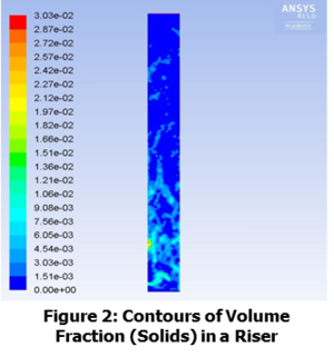
Multiphase Flow Simulations in Risers, Manifolds, Pipe Junctions, etc.
Predictive tools for multiphase flow problems are based on equations in which the mass, momentum and energy is conserved for each phase. There exist some uncertainties related to the modeling of the gas and liquid interface due to the use of over-simplified assumptions. These uncertainties can be overcome by the use of CFD, which can accurately predict physical complex phase interactions of multiphase flow in hydrocarbon transportation.


Multiphase flow can be modeled using different CFD approaches, where two favored strategies are the use of the Euler-Lagrange and Euler-Euler methods. Each of the methods has its limitations and assumptions that need to be considered when using them. In general, the determination of the fluid regime that best represents the multiphase system is the key to developing an accurate model of multiphase flow.
Cool-down & Hydrate Formation & Deposition Assessment
3D local assessment of the temperature and pressure conditions that can potentially lead to the formation and deposition of hydrates may be accomplished by CFD software. A key issue in hydrate modeling using CFD is determining whether or not the hydrate particles adhere to the solid wall. In case they adhere, it is not obvious which type particles stick to the wall. It could be the ones formed by methane phase change in contact with cold water or those formed by the light components of oil. In order to predict the hydrate formation the correct approach must be used so that these issues are adequately addressed.
CFD can be used in cool down time assessments of subsea equipment. Thermal analysis can be performed to optimize insulation thickness to delay hydrate formation and to keep the fluid temperature above the hydrate formation temperature.
Material Selection for Cold Startup
Low temperatures that result from Joule-Thomson cooling during the start-up of pressurized gas wells (especially after a subsea system blowdown), may present significant material challenges. Joule-Thomson effects can not only happen in wells, but may also occur in valves, chokes, and restriction orifices undergoing a large pressure differential. The equipment downstream of the restriction is subject to cryogenic temperatures, with several reliability issues arising as a consequence. CFD is capable of capturing the phase change and heat transfer during this process and the calculated temperature can subsequently guide the selection of materials to withstand the potential cryogenic temperatures. In this analysis the assumption of compressibility or incompressibility of the fluid plays an important role in the outcome because modeling gas as an incompressible fluid will not capture the Joule-Thomson effect.
Advanced Coupling of OLGA & CFD (Co-Simulation)
Gas-liquid slug flow can exert cyclic forces on pipe bends. Coupling OLGA and CFD enables the study of 3D effects on in-line equipment including valves, junctions, elbows, slug catchers, etc.

Knowledge of the time varying force and its distribution on the bends is highly desirable in designing the piping and piping support systems. Key issues of coupling CFD software with OLGA are:
Synchronization of the time steps in the OLGA and CFD models.
Consistency of the physical properties of the fluid components in both computation domains.
Transmission of the physical parameters at the coupling points.
There are some important factors that need to be addressed before using CFD:
It is not viable for modeling large-scale networks or for life-of-field analysis due to its computational intensity.
Averaged two-fluid formulation modeling
New mathematical models (e.g., population balance equations for disperse systems) require modification of existing/development of new CFD tools.
Advantages and Disadvantages of Using 1-D Modeling (e.g. OLGA, LEDAFLOW)
Advantages of using a 1-D modeling software are:
Current tools allow large, complex, full-scale network modeling.
The ability to include wellbore, reservoir, and process equipment operations.
An entire subsea pipeline network can be modeled, even with numerous wells and multiple lines.
Can be done in a reasonable timeframe.
These programs also enable full multi-phase pressure, volume, temperature (PVT) capability, including component tracking through the network to calculate changing compositions.
Transient operations are possible with some software, which provides data on the change in hydraulic relationship with time as well as in the flow conditions.
1-D modeling has many uses in the industry. However, it does have some limitations:
Detailed analysis of specific points in the system is not possible due to the lower resolution required to model large-scale networks.
Incapable of modeling complex geometries for specific equipment such as valve and choke internals, spools, manifolds and process equipment.
Thermal models are limited and are not always sufficient for use on complex pipe and equipment arrangements.
Conclusions
In several cases, the application of CFD in flow assurance and operability modeling can enhance the overall visibility into simulations. The use of CFD can reduce the frequency of experimentation; however, it is important to note that CFD does not replace the experimental analysis completely. This is due to the uncertainty of the input data, which creates an extensive validation and verification process; ultimately affecting the effectiveness of the mathematical model.
As new industry challenges arise, a new approach to multiphase analysis called Computational Multiphase Fluid Dynamics (CMFD) has appeared as a possible solution. The objective of this method is to model slug flows as well as the fluid regime in a pipeline; however the validation and verification of the models are still being proven. Before implementing CFD in a modeling effort, it is important to consider the intensity of the computations necessary to yield effective results.
References
http://www.ansys.com ,Simulating Erosion Using ANSYS Computational Fluid Dynamics, Vedanth Srinivasan, Ph. D. November 2014
L Xing, H Yeung, Investigation of slug flow induced forces on pipe bends applying STAR-OLGA coupling. BHR Group, 15th International Conference on Multiphase Production Technology, 15-17 June, Cannes, France,2011