HAZOP Risk Assessment via the RRR Matrix
The GATE Approach to Risk Ranking
The GATE approach to risk ranking makes risk assessment easier, more accurate, and more
repeatable by incorporating LOPA insights into the risk matrix approach.
Required Risk Reduction (RRR) Matrix
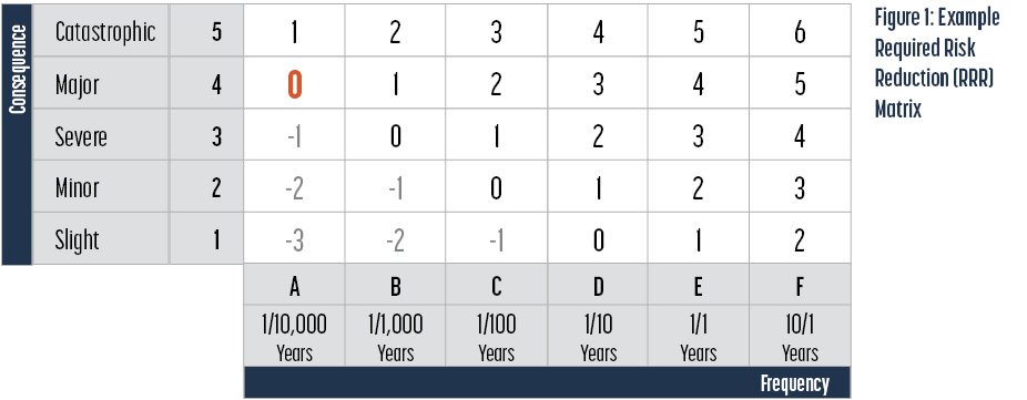
Figure 1 is an example of a required risk reduction (RRR) matrix.
The important features of this matrix are:
The frequency axis is in years/event units following a logarithmic scale, with an order of magnitude change from one column to the next.
The consequence axis is also a logarithmic scale with roughly order of magnitude differences between rows.
The numeric cell entries represent the required risk reductions (in orders of magnitude) required to reach a ‘target’ or ‘maximum acceptable’ risk level.
Generating the Matrix: Identifying the Anchor 0
Note the large bold “0” in cell A4. This is the anchor point. The selection of cell A4 as the anchor point of this matrix was determined as follows:
First, we define a “Major” event as one likely to cause a single fatality.
The average healthy 30-year-old person has about a 1/1,000 (10-3) annual probability of dying from all causes (e.g., injury, illness, etc.).
We want the workplace to be safer than the world at large, in this case 1 order of magnitude safer; hence cell A4 has a ‘0’.
This selected anchor point is for illustration only. Another point may be selected to reflect the risk tolerance of the operating company.
Once this point is selected all the others are easily populated by adding 1 when moving one cell to the right (scenario is one order of magnitude more likely) or moving one cell up (scenario is one order of magnitude more serious).
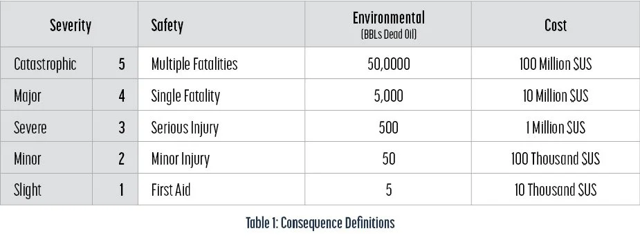
Making the Consequence Judgment
We can define the consequence categories to achieve or approximate order of magnitude steps between rows as shown in Table 1.
Consequence of Vessel Overpressure
Whereas Table 1 provides good guidance for typical scenarios, an easier approach is suggested when the scenario under consideration is overpressure.
The ASME pressure vessel code provides for a design safety factor of about 3.5 for Div 1 vessels (most vessels are designed per Div 1).
Topsides piping designed to B31.3 has a similar safety factor.
While exceeding the design pressure is a notable event, we should not expect catastrophic vessel failure at pressures less than 3 times the MAWP, assuming little corrosion and no extreme temperature.
For a major process vessel, we can estimate consequences severity as a simple function of overpressure as shown in Table 2.

Making the Frequency Judgment
Frequency of occurrence judgements are based on LOPA data as shown in Tables 3 and 4.
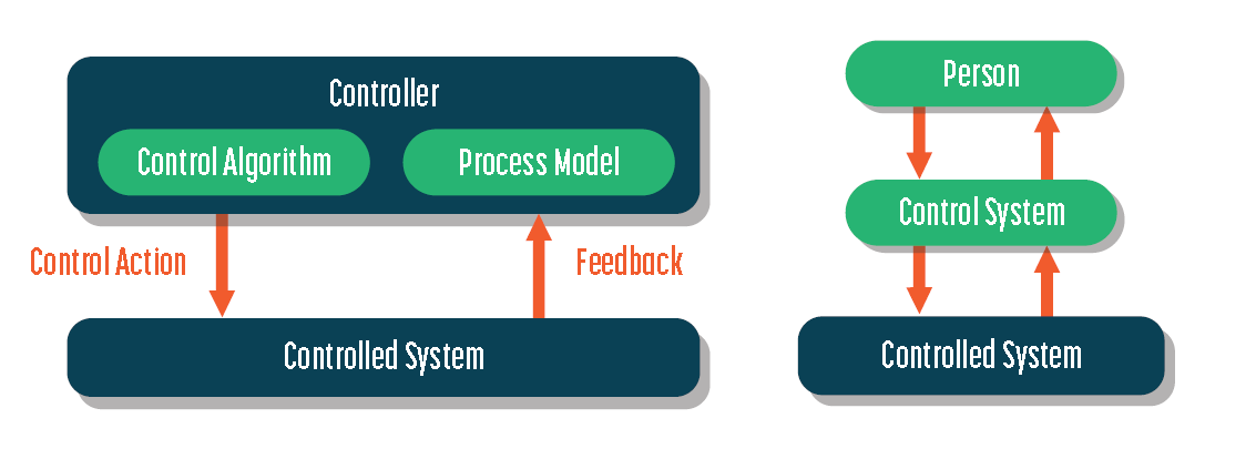
The Value of Safeguards
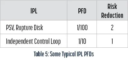
Following LOPA guidelines, only Independent Protection Layers (IPLs) are counted for assessing the mitigated risk. These have associated characteristic probabilities of failure on demand (PFD) as you can see in Table 5.


IPLs vs. Safeguards
HAZOPs identify multiple safeguards. These will not all count as IPLs under LOPA rules. In order to be considered an IPL, a protective function must be:
Effective in preventing the consequence when it functions as designed.
Can the IPL detect the condition that requires it to act?
Can it respond in time?
Does it have adequate capacity?
Independent of the initiating event.
Independent of any other IPL for which credit has already been taken.
Auditable and testable.
Safeguards Not Usually Considered IPLs
Check valves (though 2 dissimilar valves in series may be counted)
Procedures, Certification, Training
Testing, Inspection, Maintenance
Communication Systems, Signs
Active Fire Fighting Systems
Determining PFDs of SIFs
Safety Integrity Level (SIL)
The accepted reliability standard for a Safety Instrumented Function (SIF) is the Safety Integrity Level (SIL) rating. This is a measure of the SIF’s PFD. Table 6 defines SIL levels and associated PFD ranges.
For example, if we require that a SIF work effectively at least 99 times out of 100 tries, then we need a SIL 2 rated SIF.
In order to establish the SIL rating of a SIF, the failure probabilities of the SIF’s individual components must be statistically combined and a testing frequency established. The testing frequency is an important consideration. Since these systems are used very infrequently, latent (unrevealed) failure is a concern. Even the best engineered SIF cannot be expected to work forever without maintenance, and its reliability cannot be proved without testing.
The discussion below provides general guidance on what is practically achievable in
SIFs.
Achieving SIL 1: A single safety switch actuating a single SDV can generally achieve SIL 1.
Achieving SIL 2: Achieving SIL 2 may require multiple sensing devices in a voting arrangement actuating two SDVs in series, in conjunction with more onerous testing requirements. Expert guidance is required.
SIL 3 and SIL 4 systems are not commonly applied. Expert guidance is required.
Example of Applying the RRR Matrix
Hazard scenario: A blocked outlet of a relatively small vessel could yield overpressure high enough to rupture the vessel. A PSV is installed, but no other safeguarding is provided.
First, determine the unmitigated risk:
The HAZOP team identifies potential for a fatality (Row 4, Major).
The initiating event is pressure control loop failure. Per Table 3, control loop failure occurs 1/10 years (Column D).
Enter the matrix at 4D. The required risk reduction (RRR) target is 3.
The only safeguard provided is the vessel PSV which provides a 2 order of magnitude improvement (see Table 5).
That leaves a 1 order of magnitude risk reduction requirement. That requirement could be provided by a safety instrumented function (SIF) or other valid independent protection layer (IPL) with a SIL rating of 1.

Some Advantages of this Approach
The first estimate made in the example (RRR = 3) reflects the inherent, unmitigated process risk, without safeguards. This allows judgment of inherent risk that is not usually apparent in a HAZOP. A process with a very high unmitigated RRR should be considered unacceptable and require redesign rather than mitigation.
The final risk assessment reflects the mitigated risk with existing safeguards. This makes it very clear to all participants whether the risk judgment being made is the mitigated or unmitigated risk and provides clear guidance on whether the mitigated risk is acceptable.
If a recommendation needs to be made it can be much more precisely articulated. In this case, the recommendation would be to reduce risk by at least one order of magnitude.
Viking Can Help
We are on a mission to improve the way industry does process hazard analysis.
With our legacy of experience in process design, materials selection, risk assessment and systems analysis, we can provide effective and efficient design, fabrication, and operational support as the energy industry moves into a renewable future.