Induced Gas Flotation - A Unit Operations Perspective
Permitting of new and existing offshore Gulf of Mexico discharges related to oil and gas exploration and production are regulated by EPA Region 6 under the National Pollutant Discharge Elimination System (NPDES) general permit number GMG29000. This NPDES permit establishes an oil limitation of “29 mg/L average” with a “42 mg/L maximum” limit on oil and grease as measured by the hexane extraction/gravimetric method (EPA Method 1664A).
Although these discharge limits are unlikely to change anytime soon; as good corporate citizens and environmental stewards, our industry continually strives to improve the design and performance of produced water treatment systems. In addition, many operators have implemented more stringent internal standards than the permitted levels of oil and grease.
Induced Gas Flotation (IGF) has been used for Produced Water (PW) treatment for decades. The roots of flotation technology are in mining, where it has been used to enrich metal ores since the late 1800’s. The technology has evolved somewhat to better suit the special limitations presented by offshore facilities. Among these unique challenges are extreme limits on weight and footprint, as well as the need to accommodate facility motions. In order to address these issues, “Vertical Flotation Units” were developed in the early 1990’s. These units have been supplied to most offshore facilities over the past two decades, and many are now performing near their design flows.
There is now a significant trend toward more compact flotation units, as well as a need to increase the throughput of existing flotation units.
In order for flotation to occur,
A Fine Bubble Dispersion (FBD) must be generated
This FBD must be mixed with a Produced Water (PW) stream
Some time is required for bubble-droplet engagement
The FBD and PW streams must separate (the oil entrained with the FBD)
Oil rich “froth” must be skimmed from the surface of the unit
Clean water must be removed, while limiting carry under of gas and oil
On the face of it, the above items are seemingly obvious and essential. Each unit design assigns a different weighting to each of these necessary steps and performs them in a variety of ways. When one or more of these steps appears absent, or seems to have received insufficient focus in the design, it is incumbent on the Facilities Engineer and/or design team to fully understand the process as proposed by the equipment supplier.
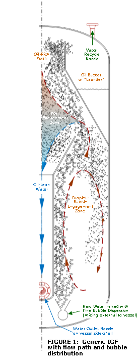
Figure 1 shows a conceptual vertical flotation unit which best incorporates the 6 process steps outlined above.
Step 1: Generation of FBD is assumed to occur using a hydraulic (eductor) based technology In some locations around the world, off gassing, as a result of pressure drops taken in the production system, can produce an FBD sufficient to affect flotation.
Step 2: Unless the FBD is formed directly within the PW (as in the case of degassing described above, or with mechanical IGF designs) it is necessary that the FBD and PW be mixed. Some unit designs on the market currently apply counter-current flow where the raw water enters in the top of vessel and the FBD is added to the bottom of the vessel. When this approach is used, care should be taken that the FBD does not form a column of less dense (as a result of the bubbles) bulk-fluid and in this way short circuit the PW stream. This short circuiting phenomenon occurs due to “bubble swarming”, a topic that is well studied and documented in the literature of flotation.
Step 3: The engagement of droplets and bubbles require time. It should be noted that smaller bubbles will likely engage more readily with fine oil droplets; however, if insufficient time is provided for this engagement, the fineness of the bubbles provides limited benefit. Also if short circuiting is occurring to a significant extent, a similar impact on unit performance will result.
Step 4: In Figure 1, a disengagement zone is shown as a zone of gradient shading from brown (oil rich FBD) to blue (oil lean PW). This semi-quiescent or laminar flow zone allows natural separation of these two streams. In some designs this disengagement is accelerated by the use of enhanced gravitational settling (light centrifugal force). At all times the tenuous bond between droplet and bubble should be remembered and significant accelerations and decelerations should be avoided to protect these bubble-droplet pairs.
Step 5: Froth skimming may carry significant water volumes over the launder and any sloshing resulting from vessel motion will add significant volumes to water carryover. The details for froth dewatering and skimming, as well as for wave restricting baffles, should be reviewed with a specific facility in mind.
Step 6: Bubble entrainment with the oil-lean PW stream exiting the flotation unit should be minimized. This is because all bubbles should be considered contaminated with oil.
Vertical and Multi-Cell IGF units have served the offshore oil and gas industry well for decades; yet, if the next crop of IGF designs are to deliver on the promised performance gains, it should be by improving each of the above process steps. In the event that one or more of the above steps have been omitted from a specific unit design, then a detailed and salient justification should be presented by the vendor.