Corrosion Testing: Methods, Results & Interpretation

It is often necessary to predict the performance of a specific material in a particular environment to determine the inherent corrosivity of the system. Such tests are often substantially different from those used for corrosion inhibitor qualification, particularly in the case of the corrosion testing of corrosion resistant alloys. Predicting corrosivity is especially important when designing subsea equipment, most of which is extremely challenging to repair or replace once it is installed. Corrosion testing is a widely used method of evaluating a material’s ability to withstand specific environmental conditions. Corrosion in field conditions can be extremely slow, thus accelerated test methods have been designed to enable evaluation and prediction of long-term corrosion behavior. In general, corrosion testing is conducted by exposing small samples of a material to the desired environment for a relatively short period of time, then evaluating the type and severity of corrosion in order to select materials or chemicals that will maximize the life of the part in question.
Main Types of Corrosion
The main types of corrosion are: general corrosion, localized corrosion, environmentally assisted cracking (EAC), and microbiologically influenced corrosion (MIC). There are many different corrosion tests, each evaluating a specific type of corrosion. Interpretation of test results is not always straightforward. Implications of the test results are dependent on the type of test used as well as the design parameters of the system being simulated. For example, corrosion can often be tolerated to an extent, but the extent depends on role of the material, its desired life span, and its design limitations. Understanding the capabilities of and differences between each test is essential for correct interpretation of test results.
Evaluation of General Corrosion
General corrosion is the “uniform” loss of material from all environment-wetted surfaces of a component. As the surface corrodes, the component thins. This is particularly troublesome for load-bearing or pressure-containing components because, as they thin, they lose the ability to perform their functions. For instance, flowlines typically undergo general corrosion and are thus designed with a corrosion allowance. This corrosion allowance can be calculated based on results of general corrosion tests and the desired life of the flowline.

To evaluate general corrosion, a small representative sample, or coupon, of the material is fabricated. Coupons are generally rectangular, measuring approximately 1” to 2” per side and having a thickness of approximately 1/8”. The coupon is measured and weighed, then exposed to the test environment for a specific period of time. The exposure period will depend on the design life of the component in question, and can range from several days to several months. Upon removal from the environment, the coupon is weighed and measured again to enable calculation of the corrosion rate using a standard formula based on the mass, surface area, exposure time and density of the material (Equation 1).
Corrosion rate is measured in mm/yr or mils/year (mpy). One “mil” is 0.001 inches, or 1 milli-inch. Acceptable corrosion rates depend on the design life of the component and the permissible corrosion allowance.
Evaluation of Environmentally Assisted Cracking (EAC)
Environmentally assisted cracking can be one of the most dangerous forms of corrosion because it can lead to catastrophic failures of system components and, unlike general corrosion, is often undetectable by non-destructive evaluation (NDE) methods. Cracking is only possible when a susceptible material is under stress in an environment conducive to cracking. EAC includes stress corrosion cracking (SCC), sulfide stress cracking (SSC), hydrogen induced stress cracking (HISC) and similar cracking phenomena.
Material susceptibility to EAC is highly dependent on the surrounding environment. Titanium, for example, undergoes hydrogen embrittlement, a form of EAC, in the presence of methanol; carbon steel cracks in acidic sulfide-containing environments; and nickel–based alloys crack in low pH brines. While hard to detect, EAC can occasionally be identified originating from pits on some alloys.
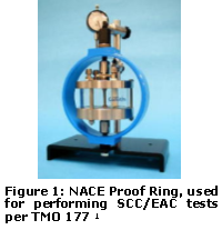
To test a material for susceptibility to EAC, it must be stressed during testing. One of the most common test methods for cracking is described in NACE TM0177. These tests are often used for material qualification, fitness-for-service (FFS) assessment, or quality assurance (QA). Four test methods are included in this standard:
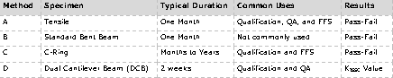
Tensile and C-ring specimens are stressed to between 80 and 100% of their yield stress. A Proof Ring apparatus is used for Method A testing from NACE TM 0177 (Figure 1) to stress carbon steel and some corrosion resistant alloy (CRA) specimens. When samples are removed from the environment, cracks and pits may be visible on the narrow portion of the sample, called the gauge length (Figure 2). Often, samples will have failed completely, broken into two halves with brittle fracture surfaces. Occasionally, the gauge length may corrode rapidly, indicating that the material is highly susceptible to general corrosion, clouding the assessment of cracking susceptibility. In the case of heavy corrosion, the duration of the cracking test should be shortened, or it may be concluded that the material will corrode away before cracking becomes an issue. In this case, a general corrosion test should be performed.

Evaluating Localized Corrosion
Pitting and crevice corrosion are two common forms of localized corrosion. Pitting is corrosion that remains localized to a small surface area, but can penetrate deeply and rapidly into a material’s bulk. Pitting is generally detectable from simple visual evaluation of a corrosion coupon or tensile specimen surface.
Crevice corrosion can occur when fluid becomes trapped in or between components and cannot easily flow or refresh. This type of corrosion is common underneath washers, around nuts and bolts, underneath disbonded coatings, etc. To test for susceptibility for crevice corrosion, artificial crevices are typically created by clamping plastic washers to samples of the material of interest, then placing these assemblies into the desired environment for a specified time (Figure 3). In severe cases, crevices may penetrate the material causing it to fail. Severity of localized corrosion can be evaluated by measuring the size and penetration depth of crevices or pits.

Microbiologically Influenced Corrosion
When a material is in long-term contact with an environment that harbors growth of bacteria or microbes, some of these organisms can contribute to corrosion processes. Stagnant conditions exacerbate the MIC phenomenon. For instance, sulfate reducing bacteria (SRB) can accumulate in water trapped in corners of carbon steel tanks or under scale buildup. These bacteria will reduce sulfate in the water to form hydrogen sulfide gas (H2S), which is highly corrosive to steels and can promote EAC. Other microbes can produce slimes or biofilms that lead to crevice corrosion, or facilitate the oxidation of metal, accelerating the corrosion rate.
The existence of MIC is often verified by extensive testing of produced fluids expected to contact a component, to identify bacteria types and growth. Coupons of the material can also be placed in the process stream or area where MIC is suspected, then removed and evaluated using microbiological techniques, such as genetic tests or fluorescence microscopy to identify types and quantities of bacteria present. (See GATEKEEPER GAT2004-GKP-2013.03, Bacteria Testing: Genetic Methods for more information)
Simulation of MIC conditions in a laboratory is not straightforward, as MIC is often a results of a combination of field conditions that provide the optimal environment for growth of corrosion-influencing consortia. Once bacterial species have been identified, the most effective mitigation methods may be determined and employed.
Conclusion
There are several common test methods for evaluating material degradation from corrosive processes. Different types of corrosion necessitate different test methods. Results of these tests inform design, materials, or chemical selection decisions that ultimately contribute to the efficient and effective operation of subsea equipment.