Shore Crossing Pipeline Cathodic Protection Design

The region in which a pipeline transitions from offshore to onshore is called a shore crossing. Often, this shore crossing zone is not very well-defined and there is much uncertainty in terms of scope and responsibilities between onshore and offshore design teams. This inconsistency can lead to issues when designing cathodic protection (CP) systems for near shore and shore crossing areas.
Figure 1 provides an example of a generic shore crossing design and is divided into three sections: shallow water, shore-water interface and on-land. This GATEKEEPER presents an overview of common challenges and solutions that are associated with each of these sections in terms of shore crossing CP design.
Section 1: Shallow Water
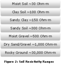
Similar to offshore and deepwater CP, it is common to utilize sacrificial anodes to protect the pipeline from corrosion. Though the protection method is similar, the design parameters will greatly change from that of an offshore design. Figure 2 provides an example of the range of soil resistivity commonly used in CP design. Each of these resistivity values play an important role in anode mass requirements, anode spacing and anode type selection.
In addition to soil resistivity variance, installation methods will have a direct impact on design parameters. For example, a highly abrasive installation, such as pipeline dragging from offshore to onshore or the use of directional drilling, will need a stronger coating, a method of protecting anodes from damage during installation or possible redundancy in the design to account for potential anode loss during pull-in operations.
While Figure 3 provides an example of typical pipeline coating types, there are additional options that serve to protect the CP system from any damage during installation or operation. This includes the application of a concrete weight coating (CWC) or the use of taper cones.
Figure 4 depicts these two options to mitigate damage during installation. CWC not only reduces anode mass requirements, but is also relatively cheap and readily available from a range of suppliers, provides additional on-bottom stability for gas pipelines, and can be applied to large thicknesses. This allows for CWC to be applied flush with anode thicknesses and so reduces the chance of snagging or damage during pull-in.
Another option is to utilize taper cones to protect anodes. While these cones do protect anodes during dragging, they are also commonly used when S-laying or J-laying pipelines to reduce hang-ups through the stinger during installation.
Section 2: Shore-Water Interface

Section 2 represents the most crucial section of the shore crossing CP design. In the case considered, a casing pipe is used as the conduit for the pipeline to traverse from offshore to onshore. While both the offshore and onshore sections of the shore crossing are designed to protect their respective sections, Section 2 can either utilize one of the CP systems from either end, have its own design or, as in most cases, utilize current from both of the Section 1 and Section 3 CP systems.
Depending on the length of the casing pipe, sacrificial anodes may be used on each end of the casing line or can be spaced throughout the length of the line. Additionally, the casing pipe may need to be electrically connected or electrically isolated from the CP systems on Sections 1 and 3, depending on the design philosophy applied. In most cases, a series of additional anodes at the end of Section 1 and the impressed current used for Section 3 is enough to protect the pipeline within the casing. However, the casing itself may need additional attention to maintain its integrity if the CP system is not initially designed to do so.
One of the most troublesome issues with casing pipes is ensuring that it remains filled with a conductive fluid. Partial flooding with seawater or splash zones caused by high and low tide will nullify the CP system and leave the pipeline within the casing at risk of corrosion. There are two solutions to this problem. These are to either completely evacuate the casing pipe, eliminating the need for CP within the casing or, more commonly, to use a conductive backfill to entirely flood the casing pipe to allow the CP system to supply current as needed. An important enabler for facilitating the CP of the line inside the casing is to minimize the casing length as much as is feasible based on the nature of the shore crossing and the local ground conditions. Protecting shorter casing lengths is typically much less challenging than protecting long cased pipe runs.
Section 3: On-Land

In most cases, onshore pipelines will be protected by impressed current protection (ICP). ICP systems are very robust and can account for seasonal and environmental changes and protect over extremely large distances of pipeline. As previously mentioned, additional power from the on-shore ICP system can be used to protect the pipeline around the shore-water interface.

It is important to note that during commissioning of pipelines, particularly onshore lines, the very final stage of the process includes the energization of the ICP system. Hence, if the CP design relies on the ICP system to protect pipeline sections that are not electrically isolated from sacrificial systems, a strain will be put on the sacrificial CP system and this will greatly accelerate anode depletion during early life. This can be controlled by applying an additional anode allowance to Sections 1 and 2, or by outfitting the system with temporary sacrificial anodes to protect the pipeline until the ICP system is operational.
Conclusion
Both impressed current systems and sacrificial anodes are effective for protecting shore crossing pipelines when used correctly. However, to achieve adequate protection the wide variety of installation methods and environmental resistivities experienced over the length of the section must be considered. Emphasis should also be placed on the shallow water sections of the line and most importantly, the transition area from offshore to onshore.
While casing pipes, pipe pull-in and directional drilling are common methods used to simplify the pipeline installation process, the pitfalls of using these methods should be considered and accounted for. Dragging lines with anodes attached to them can be detrimental to the CP system and greatly reduce coating life. Casing pipes can provide an excellent conduit when installing multiple lines in close proximity, but only partially flooding the casing, or not using a casing backfill, can cause long-term issues with CP system efficiency and performance and may result in the requirement of substantial in-service modifications and retrofits to the system.
These issues can be readily overcome, but only by ensuring that a systematic approach is taken to managing the interfaces between the traditional remits of the onshore and offshore design teams to ensure that critical items are not overlooked and that both teams understand the engineering priorities and design limitations faced by the other.