
Offshore CCUS in the Gulf of Mexico: Technical Considerations
Carbon Capture, Utilization and Storage (CCUS) plays a significant role in the energy industry’s shift towards net-zero carbon operations. Repurposing existing oil and gas infrastructures may accelerate these global efforts and is likely to provide economic advantages.
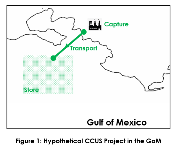
This article discusses high-level technical considerations when refitting an existing offshore infrastructure for CCUS applications. A case study on repurposing a hypothetical 20-mile,12-in natural gas gathering line in the Gulf of Mexico (GoM), shown in Figure 1, for CCUS applications is presented. All simulations in this study were conducted by GATE Energy using OLGA® and PVTSIM®.
CO2 Transport Phase
Supercritical phase transport is theoretically considered as the most cost-effective measure to transport carbon Dioxide (CO2) using a pipeline due to its liquid-like density and gas-like viscosity characteristics.
However, the high pressure and high temperature requirements for supercritical phase transport pose challenges due to the line’s 1,480 psig rating and low ambient temperature. This yields to either gas or liquid phase transport shown in Figure 2. Preheating the high-pressure liquid CO2 onshore allows supercritical phase to form, but it decreases the density which consequently would be detrimental to the transport capacity and therefore is not considered in this study.

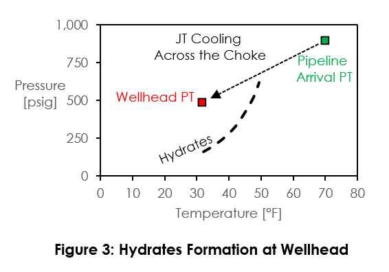
Liquid phase transport requires high-pressure pumping systems but allows much higher capacity operation; as high as 3.8 Mtpa compared to only 1.1 Mtpa with compressor-boosted gas phase transport. When using a depleted reservoir as the storage medium, high pressure liquid operation may cause several operational concerns such as low temperature and hydrate issues. This is due to the large pressure differential between pipeline and wellhead causing excessive JT cooling (Figure 3). A solution to this is to transport in the gas phase during early injection period and switch to liquid phase via high-pressure pumping as the reservoir pressure increases (late injection).
Compressor/Pumping System
Compression/pumping (Figure 4) with subcritical liquefaction discussed in the study conducted by GE Oil and Gas[3] is considered as fit-for-purpose for this case study. Compressors transport CO2 in gas phase when the reservoir pressure is low.
As soon as the reservoir pressure exceeds the minimum pressure to allow liquid-phase transport, they will be used to bring the CO2 to a subcritical pressure (typically 870 psig) and cool it to 70°F to liquefy the CO2. Pump(s) are then used to bring the dense fluid to the final pressure required to transport liquid CO2.

Control Philosophy
The operating procedures when transporting CO2 in gas phase, similar to the Dutch ROAD project[2], are:
On a shutdown, empty the pipeline to the well to minimize condensation in the pipeline
On startup/restart, start the flow to the well as soon as possible to minimize slugging, and
Assess the wellhead’s capabilities in handling slugs when refitting legacy wells.
CO2 Impurities
CO2 is rarely, if ever, transported in a pure, single-component compound. Several impurities, shown in Table 1, associated with effluents from various industries cause several operational challenges.
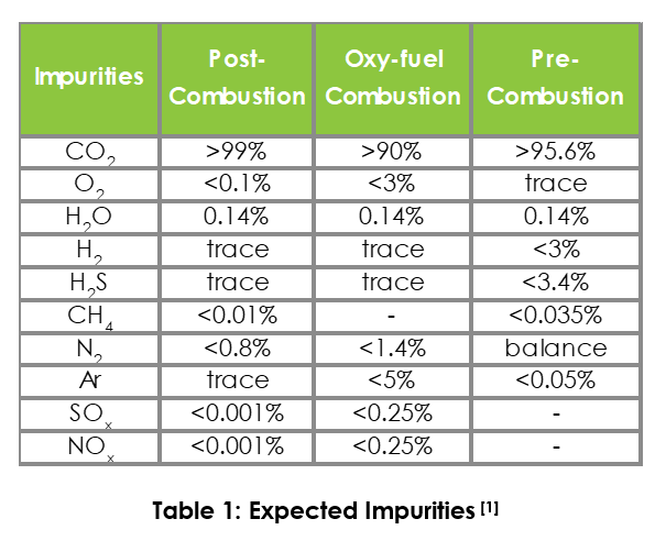
Free water is the most undesirable impurity as it can form hydrate plug(s) blocking the line when the pressure and temperature are favorable for hydrate formation as shown in Figure 3. These impurities may also present issues in undesirable two-phase flow, corrosion, and asset integrity. Figure 5 shows an example of phase envelope shift due to impurities.

CO2 Source & Preconditioning
The CO2 impurities are dependent on the type of the CO2 emitter plants[6] which require preconditioning processes prior to transportation. A few examples of potential plants for the source gas are natural gas-fired utility plants, coal-fired utility chemical plants, refineries and nuclear plants. The CO2 preconditioning requirements vary but typically consist of gas dehydration, oxygen removal, H2S removal, particulate matters removal, as well as NOx and SOx removal.
Material Considerations
Re-purposing gas transmission lines for high-pressure CO2 service requires a careful consideration of the material properties and corrosion consequences associated with a change of service. Here are some:
Wet CO2
Other Impurities (NOx, SO, H2S, and O2)
Low-Temperature Embrittlement
Mechanical Damage (Erosion, Vibration, Fatigue, etc.)
Wet CO2
Wet CO2 is extremely corrosive to carbon steel, especially at high flow velocities. Existing CO2 corrosion models such as NORSOK can be useful in providing conservative estimates of corrosion rates in wet CO2 service. The same state of knowledge is not as mature for supercritical CO2, but the expectation is that carbon steel and low-alloy steel materials, especially ferritic steels, will be similarly attacked[4].
It is worth noting that there has also been limited work in the area of qualifying corrosion inhibitors for supercritical CO2 transport, but basic autoclave exposure has shown that conventional corrosion inhibitors offer substantial protection[5]. The downside is that strongly surface-active inhibitors are known to impact downhole injectivity.
Other Impurities (NOx, SO, H2S, and O2)
There are other impurities (NOx, SO, H2S, and O2 per Table 1 above) that can also be aggressive to carbon steel pipelines. The mitigation for these is similar to that required for CO2 corrosion management – long-term reliable and effective dehydration of the process gas;
Low-Temperature Embrittlement
Well/Pipeline existing materials need to be evaluated for the risk of low-temperature embrittlement. Depending upon how the system is operated, JT cooling can be severe, potentially resulting in temperatures lower than material’s ductile/brittle transition temperature, especially when CO2 is transported in liquid phase (high pressure) and cools across a choke to be injected into a depleted reservoir at low pressure.
Existing carbon steel pipelines are typically made from API 5LX material. Unless a heat treatment specific for low temperature service was specified, the material low-temperature ductility limit is unlikely to be below -29°C (-20°F).
Mechanical Damage (Erosion, Vibration, Fatigue, etc.)
Mechanical damage (erosion, vibration, fatigue, etc.) have typically been less significant to subsea pipelines, but upstream and downstream points of attachment (particularly in the flowline jumper to the injection tree) need to be evaluated for resistance to mechanical damage. Of concern are the thermal expansion issues (pipeline walking/movement) and the stress that this puts on points of attachment such as subsea trees, risers, Pipeline End Termination (PLETs), and riser stress points.
Reservoir/Subsurface
There are several depleted natural gas reservoirs around the pipeline that may potentially be used for CO2 storage which makes refitting this line economically attractive.
A few benefits using depleted reservoir(s) are:
1. Proven storage volume
2. Abundant data on reservoir characteristics
3. Proven seal/cap formations
4. Existing legacy wells
However, in-depth investigations will be required to ensure the asset’s suitability for CO2 storage. A few examples of challenges that may arise are:
1. Low cap rock fracture pressure
2. Unsuitable well materials
3. Improper Plug and Abandon (P&A) of legacy wells in the reservoir which pose integrity risks as the reservoir pressurizes
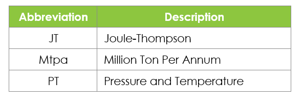
Nomenclature
References
[1] Victor E. Onyebuchi, Athanasios Kolios, Dawid P. Hanak, Chechet Biliyok, and Vasilije Manovic. 2018. A Systematic Review of Key Challenges of CO2 Transport via Pipelines. Renewable and Sustainable Energy Reviews, Vol. 81, Part 2, January 2018, pp. 2563-2583
[2] Jens Hetlanda, Julian Barnett, Andy Read, Javier Zapatero, Jeremy Veltin. 2014. CO2 transport systems development: Status of three large European CCS demonstration projects with EEPR funding. Energy Procedia 63 (2014) 2458 – 2466
[3] Cristina Botero, Matthias Finkenrath, Clarissa Belloni, Simone Bertolo, Michele D'Ercole, Enrico Gori, et al. , ASME Conf. Proc. 2009, 517: Thermoeconomic Evaluation of CO2 Compression Strategies for Post-Combustion CO2 Capture Applications, 2009
[4] “Corrosion in Supercritical Carbon Dioxide: Materials, Environmental Purity, Surface Treatments, and Flow Issues”, 10-872 NEUP, U. of Wisconsin, K. Sridharan et al, 2013
[5] “Strategies for Corrosion Inhibition of Carbon Steel Pipelines Under Supercritical CO2/H2S Environments”, Choi, YS, et al. Corrosion 75(10), 2019
[6] L.C. Jordan, A.B. Darwin, H.J. Duhon. 2009. “Deepwater Flue Gas Injection for Enhanced Oil Recovery: Corrosion Management and Material Selection Issues”. Paper No. 2831. NACE International