
Placement Of Sulfate Removal Units In Waterflood Systems

Deepwater seawater injection projects, whether subsea or dry-tree developments, generally face the dual challenge of scale control and reservoir souring. These challenges are such that practically all deepwater seawater injection projects are forced to adopt a proactive approach that considers the options of designing for production well scale squeezes or applying sulfate removal for scale control and the use of either nitrate injection or sulfate removal for souring control.
Sulfate removal units (SRU) are able to reduce the sulfate content of injected seawater by filtering the water prior to introduction downhole. There are many benefits in terms of both flow assurance and economics to be gained from sulfate removal, including the following:
Reduction or elimination of scale inhibitor squeeze treatments. Advantages include avoiding the cost of such treatments, deferred production during treatments, monitoring of residual scale inhibitors, and potential reservoir damage.
Reduction or elimination of co-precipitation of radium 226. This otherwise results in the formation of radioactive barium sulfate scale, generating an increased naturally-occurring radioactive material (NORM) hazard and increasing subsequent handling, decommissioning and disposal costs.
A reduction in the risk of adversely affecting well productivity and ultimate recovery as a result of scaling and subsequent unsuccessful or less than optimal well work-overs.
There are two options when it comes to the placement of the SRU in the water injection system. The first option, presented below, shows the SRU upstream of the deaerator tower.

The second option has the SRU downstream of the deaerator.
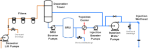
SRU Placement: Option 1
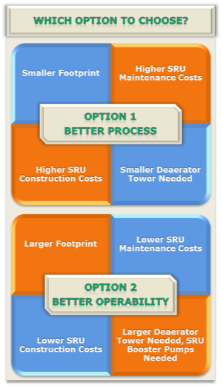
Option 1 is a better process configuration than option 2 due to the placement of the SRU, the topsides cooler, and the deaerator. SRU membranes perform better in colder seawater, while deaerator systems perform better with warm seawater. The topsides cooler uses the seawater to cool the production stream. This cooler eliminates the need for a separate cooler skid for the topsides and so decreases the footprint of the system. The topsides cooler is in the ideal position for this option where cool seawater enters the SRU and hot water enters the deaerator. Since the SRU is upstream of the deaerator tower, defoamer may be applied to treat foaming in the deaerator.
This design option also minimizes the weight and space of the water injection system since the SRU is placed earlier in the stream. All equipment and piping before the SRU is required to be 33% larger than the equipment and piping after the SRU to allow for the SRU reject stream.
Option 1 does not have an optimum operability configuration.
This option has the disadvantage that aerated seawater flowing through the SRU will require corrosion resistant alloys such as 25% Cr super duplex stainless steel to prevent corrosion. This will result in higher CAPEX costs than units handling deaerated seawater.
With aerated seawater come aerobic bacteria, which are more likely to produce solids that will plug the SRU membranes. Routine biocide treatments will reduce the amount of fouling, but the life of the filters is still likely to be reduced over deaerated systems for all but the most stringently operated systems. Membrane replacement is a high-cost exercise, where this configuration will often require membrane replacement between every 2 and 4 years.
Hypochlorite is often used upstream of the seawater lift pumps in order to control macro organisms and bacteria. If hypochlorite is used, care must be taken as SRU membranes rapidly degrade when exposed to free chlorine. Oxygen scavenger will need to be used upstream of the SRU to neutralize the hypochlorite. To monitor this balance between the oxygen scavenger and hypochlorite, a redox meter will be needed immediately before the SRU.
SRU Placement: Option 2
Option 2 is a better operability configuration than option 1. Seawater entering the SRU will be deaerated, meaning that bacterial fouling of the SRU membranes is generally easier to control. Typically, a well-operated facility with this configuration will need to replace membranes every 4 years, although some systems have shown longer life.
Other benefits of the deoxygenated seawater includes elimination of the need to remove free chlorine ahead of the SRU and the downgrading of SRU materials.
However, option 2 does not have an optimum process configuration.
The placement of the topsides cooler is not ideal and has minimal effect on the water injection system. If the deaerator tower is more important than the SRU, a heat exchanger may be placed before the deaerator to optimize the deaerator tower performance.
The deaerator will need to be a minimum of 33% larger to allow for the SRU reject stream. This can be a significant challenge for floating production facilities where weight and space may be limited.
DBNPA is the only approved biocide that may be used in the SRU. Since the dearator tower is upstream of the SRU, only DBNPA can be used to treat the tower, which is less effective than alternatives such as THPS and glutaraldehyde. Water injection defoamer is also not approved to be used upstream of SRUs; hence, the size of the deaerator may need to be further increased.
Gas stripping deaeration towers may not be able to used with this option due to possible hydrocarbon carry-over and resultant damage to the SRU membranes.
Water leaving the deaerator tower will not have enough pressure to get through the SRU; therefore, SRU booster pumps will need to be installed upstream of the SRU.
Conclusions
The decision as to which SRU placement option to adopt is generally based on the weight and space limitations of a particular facility. Where this is at a premium then Option 1 is often preferred due to the decrease in overall weight and footprint of the system. However, where this limitation does not prevail then Option 2 is more attractive due to the generally lower CAPEX and OPEX associated with this arrangement.