
Gas Pipeline Drying Methods
Achieving the ideal dryness for a subsea natural gas pipeline is a crucial step not only for commissioning of a pipeline, but also for is subsequent integrity management. Attaining the correct dryness level can help inhibit microbiologically influenced corrosion (MIC), hydrates and other issues.
Drying of a pipeline is usually completed in stages that involve one or more of the following techniques: pigging, methanol/glycol swabbing, air drying, vacuum drying and nitrogen packing.
Selection of methods for drying is often driven by economics and time restraints, without sufficient consideration given to operability and corrosion issues.
Determining Dryness Criteria
There are many factors that can influence dryness criteria. Type of hydrocarbon, hydrate formation conditions, corrosion studies, pipeline topography, piggability and environmental regualtions are considered. During commissioning, pipelines are filled with commissioning and hydrotesting fluids that must be treated and removed from the pipelines prior to commissioning and start-up.

The makeup of these fluids must be considered when determining dryness criteria. For natural gas pipelines, the generally accepted moisture limit is around 40 lbs/mmscf or a dew point of –4°F (-20°C). Dew point is a major consideration when evaluating pipeline dryness criteria. A dew point below the hydrate formation curve at expected operating temperatures and pressures is desired. A dew point of -4°F (-20°C) is usually attainable and sufficient for most applications. Tables for converting dew point to moisture content are readily available, and are useful tools to assist in determining dryness criteria.
Methanol and Glycol Use
Methanol (MeOH) or glycol will normally be used to dewater equipment that carries gas (pipelines, jumpers, etc.) to prevent hydrate formation during the bulk dewatering phase of the commissioning process. A comparison between MeOH and glycol can be found in Figures 1 and 2. During pipeline conditioning, MeOH or glycol slugs will be pigged through the system to apply a combined methanol or glycol/hydrotest water film on all internal surfaces. This process is referred to as methanol or glycol swabbing.
The main disadvantage to MeOH or glycol swabbing is the assumption and estimation of a uniform hydrotest fluid film bypass over the length of the equipment, typically a 0.1 mm film. Therefore glycol/MeOH volumes are calculated to provide a percent volume of hydrotest fluid in the last glycol/MeOH slug in the dewatering pig train. The residual water left from this method causes swabbing to be somewhat ineffective when done alone, but in combination with other methods the pipeline can be ready for start up quicker.
Flexible pipelines present an additional challenge due to the corrugation volume which must be treated. Additionally, the volume of glycol/MeOH required to treat the flexible is calculated with respect to dewatering speed and direction (subsea to FPSO for example).
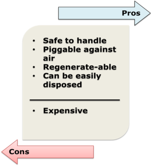
Mono-ethylene glycol (MEG) is usually the fluid of choice for swabbing. MEG is typically chosen because it is easier to handle than methanol and can be regenerated. Generally after MEG treatment, the equipment in final park condition is to be exposed to a minimum MEG concentration of 80%, where this value is to include the effect of remaining hydrotest water on its dilution. The reason for this concentration is that MEG requirements for hydrate control are a typical 50% rate in total fluid, whereas a minimum 80% concentration is required to control the propensity for bacteria to grow in the solution. Where MEG is used, it must meet stringent specifications since MEG is produced with gas and typically processed by regeneration equipment.
Air Drying
Drying pipelines initially involves pigging with dry air. The dry air will absorb the water left from the dewatering phase. The process of running pigs and dry air through the pipeline is continued until the desired dew point at the outlet is met. The outlet should be topsides or onshore though an open pig receiver door The disadvantage to this method is that it requires a large air drying spread and may take a long time. Also, air drying suffers from one major flaw, typically the beginning and end of the pipeline is dried quickly and the center becomes saturated. This is because the pressure is higher in the center sections of the pipe, therefore the air cannot absorb as much liquid. When the air reaches the outlet, where the pressure drops to near ambient, the air can absorb more water vapor. Therefore, the center of the pipeline is not dried effectively. Moisture content measurements at the outlet can sometimes not reflect actual moisture content in the pipeline. For these reasons it is necessary to perform a soak test. To reduce drying times it is often necessary, due to pipeline profiles, to run multiple pigs to remove as much remaining free water as possible.
A soak test is performed by shutting in the pipeline for 12 hours, and then an air volume equivalent to the pipeline volume is passed through the pipeline at the lowest possible pressure while monitoring the dew point of the air at the discharge point. If the dew point at the discharge point conforms with the dryness criterion, the drying campaign is complete.
Vacuum Drying
The principle behind vacuum drying is to significantly reduce the pressure in the pipeline which will cause the water in the line to vaporize. The water vapor is removed by allowing the vapor to flow towards the vacuum equipment, causing the water to condense and be collected at the exhaust point. By turning the water to vapor, this method has an advantage over others in that all free water including low spots and water trapped on the walls is removed. The disadvantage of vacuum drying is that the final dryness is dependent on the vacuum pressure levels that are achievable. If a low enough pressure is not attainable, vacuum drying is not effective. Large deep water systems typically cannot be effectively vacuum dried.

Nitrogen Packing and Purity Criteria
A pig train driven by nitrogen is commonly run through a pipeline after dewatering is completed and dryness is confirmed. Once dewatering and drying is complete, air will be left in the pipeline unless swabbing is performed, whereby the pig train may be propelled by N2. In deep water and remote locations, or where N2 tanks are not desirable, N2 generation equipment will be required. Typically N2 generated from a membrane will have a dew point of -40°C. Liquid N2 tanks typically have a dew point of -70°C. Bottled pure N2 is preferred because of its low dew point, but logistics often do not allow for the use of bottled N2.To reduce the temporary equipment requirements, to fit on a vessel for example, and achieve suitable dewatering speed, it may be desirable to initially swab with dry air followed by N2 inerting. N2 is used to pack the system and form a barrier between the hydrocarbons and O2 at first introduction of production gas to the pipeline. Packing pressure is often determined to avoid large pressure drops over chokes at start up. N2 is used because it is inert, non-corrosive and has less risk of combusting compared to using air.
A minimum of 95% N2 purity is required to maintain the system below the Lower Explosion Limit (LEL) at start up. Ideally 97% should be used as the target. The LEL of Methane is 5%.
The final step for drying of a pipeline is the introduction of export gas per the receiver's specification. When the dry export gas is introduced it will sweep out the remaining N2 to the receiver during startup. Typically, the moisture limit of export gas is around 2 lbs/mmscf.
Conclusions
A drying campaign is crucial to the commissioning of every natural gas pipeline. When done correctly, effectively and efficiently, the results can prevent hydrate formation during start up and also protect the ongoing integrity of the pipeline and save operating expense over the life of the system.