
Introduction To Risers
RISER PURPOSE AND OVERVIEW
Utilized in a number of configurations, a riser presents the operator with a conduit that serves as the main method of hydrocarbon transport from the ocean floor to the host facility as well as a method of external media introduction such as chemical and water injection. Considering the large number of applications that risers have, as well as the dynamic environment associated with subsea oil and gas exploration, it comes as no surprise that the down selection of various riser designs can be a complex process requiring extensive knowledge of each riser style. To aid in this design process, a number of standards have been developed to ensure safe practices throughout design and installation. Such standards and recommended practices can be seen in API RP 2RD, API RP 1111, ASME B31.4 and ASME B31.8 which should be utilized to keep safety at the forefront of the design.
TYPES OF RISERS
There are currently a number of riser configurations that have been utilized in subsea oil and gas production. Attached, Pull Tube, Steel Catenary, Top-Tensioned, Flexible, and Hybrid Tower risers will be introduced in this article with respect to down selection factors such as those listed in Figure 1. These factors, though a good indicator of considerations that must be made during design, should not be considered comprehensive. Rather, factors such as these should be weighed throughout the selection process to ensure the most beneficial style of riser is selected and developed. Ultimately, each design will have a list of factors similar to these that is specific to the requirements of the system and must be satisfied to ensure riser selection may be made safely and confidently.

ATTACHED AND PULL TUBE RISERS
The attached and pull tube risers may be considered as the simpler approaches to riser design when comparing to some of the modern technological advances in the industry. Utilized on fixed platforms, compliant towers, and concrete gravity structures, these two designs are statically mounted to the supporting platform substructure and are limited to water depths (approximately 3,000 feet maximum) where these towers can be deployed. Both rely on ROV installation campaigns with the attached riser being installed in sections starting at seabed while the pull tube design may be pre-installed or retrofitted to the tower after its installation.

The methods for both designs and overall function are conceptually simple. The attached riser utilizes clamps, typically with polymer liners, to fix the riser pipe to the tower. The pull tube differs in that, although it is mounted statically to the tower, it serves as a conduit for a smaller diameter flowline to pass through. The flowline is typically pulled through the riser via a high capacity winch connected to the messenger wire of the flowline. Both riser designs are presented schematically in Figure 2 while highlights for each are presented below.

Although the towers utilized in both designs are considered to be very stable, a 2% water depth translation is typically observed at the topsides in severe weather conditions which can place large fatigue loads on risers. This must be carefully considered during the design process to ensure the stress levels due to cyclic fatigue on the riser material is kept within acceptable limits.
STEEL CATENARY RISERS
The steel catenary riser (SCR) is a design that appears simple in concept, but can quickly become more complex as deeper waters are considered. Consisting of a steel pipe free hanging from a platform, careful design considerations must be made to ensure adequate wall thickness selection and weld standard compliance, both of which are crucial to safe operation. Applicable to a wide number of platform designs, SCRs are generally utilized with semi-submersible floating facilities and are an effective and reliable option when used with deepwater wet tree systems.

Proving to be an excellent alternative to the more costly flexible riser, the SCR can provide a method of hydrocarbon transport in depths exceeding 3,000 feet and can be considered for greater depths with the use of buoyancy supporting jackets that help to alleviate the large tensile forces generated proportionally to riser length. Pairing an SCR with a flexible joint or stress joint at the topsides also proves advantageous to the overall design in that bending stress is minimized during heaving motions of the topsides while still allowing for the riser to be raised and lowered to the seafloor during such motions. This movement, however, will continually weaken the riser due to cyclic fatigue and must be accounted for during material property selection.
SCRs, unlike flexible risers, are generally not wet stored prior to installation. This necessity means complete installation normally occurs during a single project phase involving a welding process that joins adjacent sections of pipe before they are lowered to the ocean floor in a J-lay or S-lay fashion. In some cases, where design parameters such as pipe diameter allow, SCRs can also be laid from a spool (similar to flexible risers). Figure 3 illustrates the layout of an SCR.
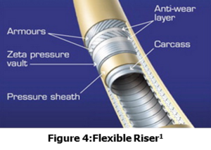
FLEXIBLE RISERS
Composed of multiple spiral laid materials as shown in Figure 4, the flexible riser demonstrates excellent bending capacity while still possessing exceptional strength, making it extremely versatile with regards to application. Originally designed for flowline applications between vessels, the flexible riser has gained popularity in deep water due to its ability to withstand significant dynamic environments making it an excellent choice for harsh sea conditions.
Installation methods are also a positive aspect of flexible flowlines in that normal installation campaigns can typically be completed much more quickly than other risers due to the high spooling capacity and offload speeds that can average up to 500 meters per hour. The ability to be wet stored (material choice permitting) prior to installation also proves a benefit of the flexible pipe in that it allows for schedule flexibility during an offshore installation campaign.
Throughout the design phase of flexible pipe, careful consideration must be made with regards to the hydrostatic pressure that will be observed at full depth. As depth increases, the pressure differential becomes greater and supporting layers, such as the pressure sheath and armor layers, must be designed with a thickness that is capable of withstanding the associated forces of deep water. If one of these supporting layers were to not be adequately designed to withstand these forces, the pipe would be crushed as it was lowered to the sea floor. Sufficient designs, however, have proven the flexible riser to be applicable to depths of 10,000 feet and operating pressures of 10,000 psi at 300oF.
A design characteristic that may deter the use of flexible pipe in some applications is the need for bend stiffeners or Bell mouths. Utilized to ensure that the stress throughout the joint is kept at a minimum, these stiffening methods should always be considered during the design process though topside space requirements may cause complications. A method of venting the annular space of the pipe layers should also be implemented to ensure any gas migration through the pressure sheath can be vented at the topside.
TOP TENSIONED RISERS AND HYBRID RISER TOWER
A top tensioned riser (TTR) is a vertically oriented riser (either flexible or steel pipe) commonly associated with tension leg platforms and spars. Utilizing buoyancy cans or hydro-pneumatic tensioners, large tensile forces are placed on the riser holding it in position for production. By utilizing such top tensioning devices, the risers are allowed to axially translate, or stroke, with respect to the platforms motions.

This makes the TTR a primary consideration where sea conditions are consistently at moderate levels.
Similar to the TTR, a hybrid riser tower utilizes top tension via buoyancy cans to relocate the primary connection point between floating vessel (typically FPSOs) and the production flowlines. Shown in Figure 5, the concept behind a hybrid riser is promising. Raising the connection point to a few hundred feet below the surface greatly reduces the time needed to make connections compared to full depths potentially approaching 10,000 feet. A complication of the hybrid riser, however, comes at the connection point of the buoyancy can to the riser pipe. Heavy chain is utilized as the primary connection which would intuitively allow for translation of the buoyancy can due to currents and forces during connections. The longer vertical riser lengths associated with the hybrid design, however, present proportionally large weights that have to be overcome with buoyancy to hold in tension. This places the chain links under very large tensile loads. These loads can effectively fuse the links of chain together and impose stress throughout the links cross sectional area during motion. If this stress exceeds the material properties of the chain links, failure and complete loss of the riser can occur.
Highlights for the top tension riser and hybrid riser are shown below.

CONCLUSIONS
With offshore oil and gas recovery pushing the limit with deeper and deeper water, it comes as no surprise that the technology regarding risers has evolved to meet the demands of harsher environments. Although the list of options is extensive, careful consideration of selection factors aids in down-selecting to the most applicable designs. Understanding the overall design requirements of the riser is the main consideration when it comes to selection. From there, the system can be broken down further, continually weighing alternative methods, until the best design is chosen and implemented.
REFERENCES
Bai, Y., & Bai, Q. (2010). Subsea Engineering Handbook. Gulf Professional Publishing.
http://www.cortest.com/inside.htm