
Blockage Remediation Part 1: Blockage Characterization & Detection
In spite of robust design, adequate infrastructure and a well planned and executed operating strategy, partial or fully blocked pipelines, with loss of production in many cases, is a reality. This series of two articles discusses the diagnosis, detection and remediation of oil and gas production system blockages in detail. The current issue focuses on blockage characterization and detection.
The first and one of the most important steps in the blockage remediation process in oil and gas production systems is the understanding of the nature of the blockage. Blockages can be of different varieties: organic, such as asphaltenes, waxes or natural gas hydrates; inorganic, such as sands or scales or products formed due to the incompatibility of chemicals or well streams; mechanical such as collapsed pipe/risers or failed valves; and/or a combination of all of these.
Field experience has shown that the initial assessment of the blockage nature is, in many cases, not accurate. This is often due to a lack of understanding of the system and of its prevailing flow assurance and production chemistry challenges. This uncertainty means that decisions taken immediately after a blockage is identified often worsen the blockage conditions, rather than helping in its remediation.
BLOCKAGE CHARACTERIZATION
Several aspects are necessary to characterize the blockage effectively and determine the degree of the blockage in the system. These include produced fluid characterization and interaction with injection chemicals, system architecture and layout, system operating conditions, and production history.

PRODUCED FLUID CHARACTERIZATION & INTERACTION WITH INJECTED CHEMICALS
Understanding of the produced fluid characteristics and their interaction with injected chemicals are necessary to determine the potential risks of precipitation, deposition and accumulation of solids in the producing system. Tracking of production system operating parameters along with continued monitoring of the changes in the produced fluids helps significantly in the effective assessment ofthe nature of the blockage.
In the absence of such a program, it is necessary to estimate the fluid characteristics from the original fluid sample testing, previous well testing, and the current production reports (e.g. water-cut, API gravity, gas to oil ratio, etc.). Simulation and fluid modeling may also help in this endeavor. Other fluid testing reports that can be of benefit include: Reservoir fluid PVT analysis, compositional analysis, wax/asphaltene characterization (i.e. AOP, Cold finger, SARA) and deposition testing, produced water chemistry testing, rheology analysis (i.e. viscosity and gel strength), chemical compatibility assessment and injection philosophy, production chemical selection studies, scaling and corrosion studies and flow assurance steady state and transient analyses.
SYSTEM OPERATING CONDITIONS
Operating temperatures, pressures and flow conditions along the production system need to be known in order to effectively determine with better accuracy the nature of the blockage. For instance, pressure and temperature driven blockages such as asphaltenes, wax and hydrates may occur simultaneously at certain operating conditions, but can require different methodologies and tools for their remediation.
The right interpretation of the prior system conditions is paramount to developing effective intervention and remediation strategies for the potential blockage. Experience has shown that in many cases the operating conditions are misunderstood and subsequently wrong actions are undertaken. This can be further exacerbated when the outputs from faulty pressure and temperature sensors or inadvertent valve operations are not recognized and accounted for.

SYSTEM ARCHITECTURE & LAYOUT
System layout, hardware/jewelry/equipment distribution and topography are important factors in determining the probability of blockage formation. Flowline Inclinations, low spots, heat sinks, dead-legs, flowback points, piping joints downstream chokes, leaking valves and umbilical/flying lead connections are just some of the locations where blockages can form or may be induced. Typically, these are locations where intervention points are non-existent; therefore, remediation operations are time consuming and costly.
Understanding the system is of high importance and a systems approach evaluation is necessary to determine the at risk locations. This will enable deployment of preventive and corrective measures when needed.
PRODUCTION HISTORY
Information regarding past events, changes in operating philosophy, daily production rates, chemical injection rates and prior interventions are valuable at the time of the blockage nature assessment. Changes in production characteristics, like new wells brought online, increases in water cut, gas to oil ratio or the suspension or contaminationof injected chemicals may provide hints on the blockage type.
Time elapsed since the blockage started to form and the time it is noticed may give insights into the nature of the blockage itself. For example hydrates are expected to form, deposit and accumulate typically in a matter of hours, often under transient conditions, whereas asphaltenes and wax can take weeks or months to form and require sustained conditions for deposition to occur.
BLOCKAGE DETECTION
Once the probable nature of the blockage is ascertained through fluid characterization and examination of the operational history, the next step in the blockage remediation process is to identify the pipeline/s with blockage/s followed by the determination of the location/s of the blockage/s. An accurate location of the blockage would lead to the selection of the most appropriate blockage remediation strategy and optimal use of the available resources. This in turn leads to savings in cost and time for the operator.
As a first approach, devise blockage detection options that use the existing facilities and that can be readily executed. Then, If the options are deemed impractical with a high risk/reward ratio or do not result in a desirable outcome upon implementation, more advanced tools or techniques need to be considered for use. Blockage detection methods include: depressurization, pressurization, mechanical methods, pigging gels, pipeline scanning and thermography, and modeling and analysis.
DEPRESSURIZATION
Depressurizing the line with the blockage on one or either sides and analyzing the pressure response on the other side provides vital information on blockage location. The need to use gas-lift (if available) in depressurization should be evaluated, especially in liquid dominated systems. There could be a delay in pressure response, sometimes in the order of days depending on the nature and size of the blockage. This method is most suited for hydrate blockages.
PRESSURIZATION
In the event of no response to depressurization, pressurization can be performed using one or a combination of the following methods:
Topsides/subsea gas injection
Topsides/subsea chemical injection
Sending alternate pressure pulses to the blockage
The last method is most suited in locating non-hydrate blockages, but can be applied to detect hydrate blockages as well under certain conditions.
MECHANICAL METHODS
Insertion of equipment like a wire, rod, coiled tubing etc. can help in mechanically locating the blockage. However this method is only suited for blockages that are close to the access insertion/access point.
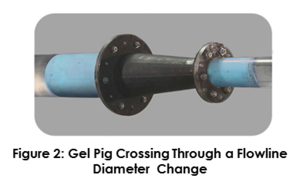
GEL PIGS & PRESSURE MONITORING
Gel pigs can be used specifically when partial communication exists through the blockage. The injection of gel pigs and a continuous monitoring of the pressure can indicate with relatively high accuracy the location and distribution of the blockage along the flowline. Furthermore, gel pigs can be engineered to carry solvents that may speed up the initial blockage remediation process.
PIPELINE SCANNING & THERMOGRAPHY
Usage of some of the advanced pipeline scanning tools and careful analysis of their outputs provides details of both the location and nature of the blockage. This non-intrusive technique suits lines that are not buried or which can be dredged for access. Measure of the densities of the contents in the flowline provides insight into the nature and location of the blockage.

Thermography uses infrared emissions to record fluid temperature along the pipeline, where step changes in temperature suggest the possible presence of blockages.
MODELING & ANALYSIS
Modeling the blocked line or the entire system using “as-built” data and analyzing the sequence of operational events that led to the blockage provides useful insight to the location of blockage/s in the system. Benchmarking of the events preceding the blockage by means of simulation provides a good starting point when other techniques are not suitable because of cost or accessibility. The pressurization and depressurization attempts to locate a blockage may also be simulated. Correlating the actual pressure responses with those from the analysis is recommended for accurate prediction of blockage location.
CONCLUSION
Blockages can occur anywhere in the production system and impact field economics. Before any remediation efforts are implemented, it is important to determine what is contributing the formation blockage and to identify its nature and location. Care needs to be taken at this stage to ensure that the detection method itself will not make the blockage worse or harder to remediate in future.
The next issue in this series discusses the blockage remediation methods in general and selection of a fit-for-purpose method depending on the urgency, available facilities, cost involved and whether or not the production is impacted.
REFERENCES
http://www.tracerco.com